Results


#1. In VISR flex temp entered is 34. While entering runway TAT falls to 32°. When thrust levers set between clb and flex what thrust will be given by the engine
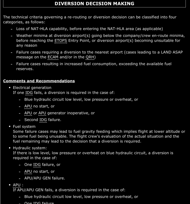
#2. in a edto flight you get blue hydraulic failure. will you divert?
increase in fuel consumption and fma unreliable
slats slow
any failure with fuel consumption increase we divert
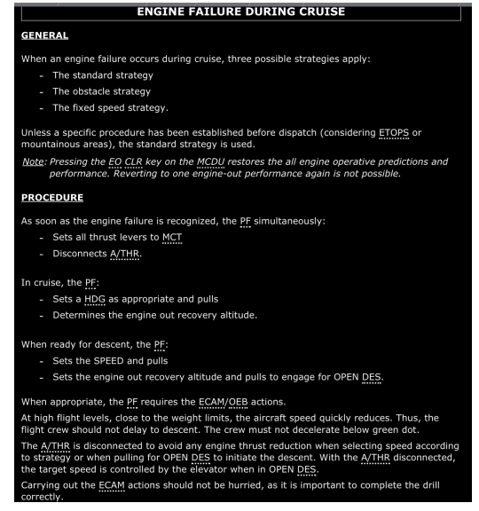
#3. Eng fail in cruise. Immediate actions
set all thrust lever to mct
disconnect a/thr
set spproriate hdg
determine engine out recovery altitude
WHEN READY FOR DESCEND
SET SPEED AND PULL
SET ENGINE OUT RECOVERY ALTITUDE AND PULL TO ENGAGE OPEN DES
#4. Reservoir pressurization
HP bleed air from engine one pressurizes the hydraulic reservoirs automatically
If the bleed air pressure is too low, system takes bleed, air pressure from cross bleed duct
(DO NOT GET CONFUSED WITH HYDRAULIC SYSTEM PRESSURIZATION THIS IS THE RESERVOIR)
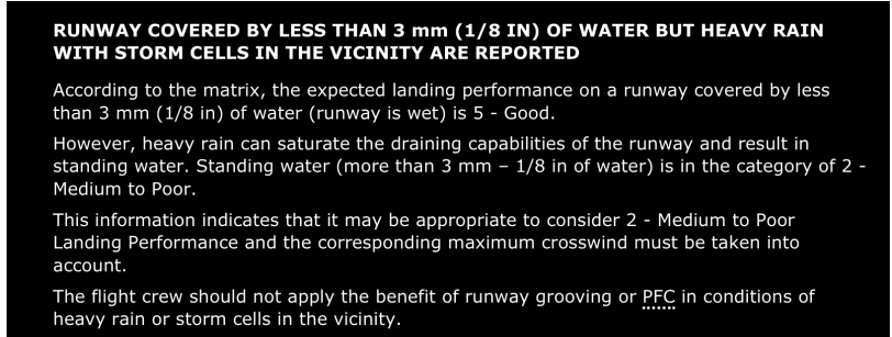
#5. Wing anti ice indication on ewd when
WAI APPEARS ON EWD WHEN THRUST LEVER IN TOGA OR FLX/MCT DETENT
#6. Missed approach which colour on f plan page
FCOM>SYSTEMS>FLIGHT GENERAL>PILOT INTERFACE>NAVIGATION DISPLAY>FLIGHT PLAN DISPLAY COLOURS
#7. PRIMARY FLIGHT PLAN COLOUR IN MANAGED MODE?
STEADY GREEN
#8. PRIMARY FLIGHT PLAN COLOUR IN SELECTED MODE?
DASHED GREEN
#9. colour of alternate flight
Dashed blue
#10. color of OFFSET flight PLAN
Steady Green Flightplan dash green
#11. Colour of temporary flight plan
Dashed yellow
#12. colour of engine out sid (not inserted)
Steady yellow
#13. Colour of secondary flight plan
Steady dimmed white
#14. Colour of Abeam Radial flight plan
Dashed blue
#15. Qdm
15 min supply
#17. Emergency response plan
ops a
emergency response manual
A formal plan that defines the action taken following an emergency situation to ensure orderly and efficient transition from normal to emergency operation, and then safe continuation of operation or the return to normal operation as soon as possible
#18. due to some failure what vapp to enter in MCDU. Ldg distance proc not displayed
VLS is the lowest selectable speed.
VLS is used to determine the Final Approach Speed (VAPP) in normal conditions.
REFERENCE SPEED (VREF).
VREF is equal to the VLS of CONF FULL.
VREF is used to determine the Final Approach Speed (VAPP) when a system
failure affects the landing performance
#19. Rapid brake application what indication
#20. Flying to some airfield. Rain is expected. What calculation will you do
#21. LDA silchar is 1986m . FLD is 1957m.
#22. Weather avoidance
#23. Eng pump fault light
#24. Mr. A Enters the ac and abuses the crew . Mr A is
#25. Vobl landing . Rwycc 3
#26. RNP approach
#27. Centre tank transfer valve
The transfer system controls the flow of fuel from the centre tank to the inner tanks. The fuel level sensing control unit also called FLSCU has automatic control of the transfer valve.
WHEREAS
FQIC =FUEL QUANTITY INDICATION CHANNEL
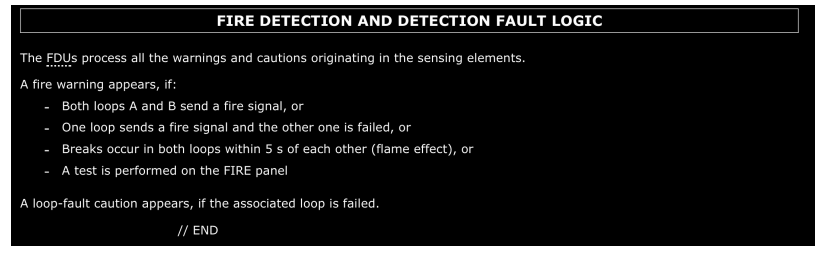
#28. Fire warning detection
Fire detection Unit Process all the warnings and cautions originating in sensing elements
Fire warning appears if both loops A and B send a fire signal or
one loop sensor, fire signal and the other one is failed or
brakes occur in both loop within 5 seconds of each other Or
test is performed on the fire panel
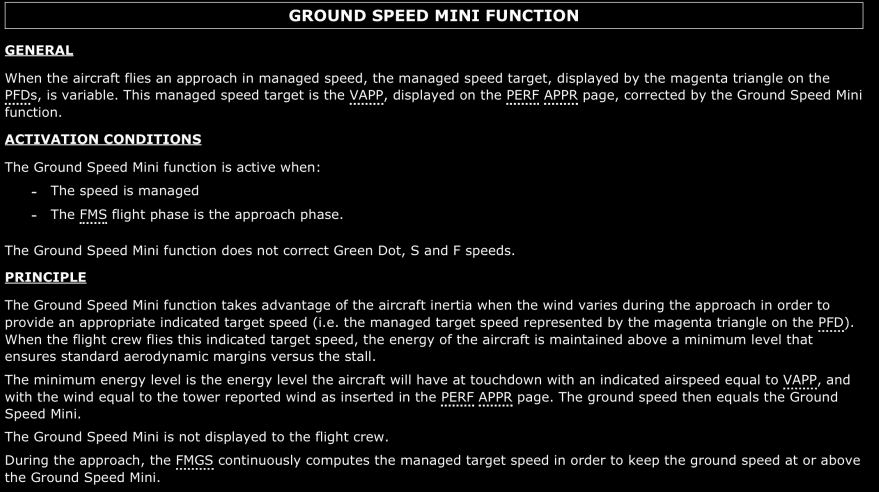
#29. GS mini function with
#30. Flying from Chennai to Singapore at FL330. Need to climb to FL350 which page to use in efb
#31. Mix irs
Each FMGC receives a position from each of the three IRSs, and computes a mean-weighted
average called the “MIX IRS” position:
#32. In IAE 60% to 74% cannot be set
Keep Out Zone is for protection against fan flutter,
• When on ground at low speed (less than or equal to M 0.1), the Electronic Engine Computer
(EEC) protects engine against fan flutter.
In so doing, the EEC prevents the engine from being stabilized between an approximate range
of 60 % to 74 % N1 (depending on the outside air temperature).
Therefore, during engine acceleration on ground, the pilot may notice a non-linear thrust
response to thrust lever movement and pilot can not set power in the range of 60% to 74% N1
on ground
#33. In edto when can we ETP points
#34. SFCC1 failure – flaps/slats operate at half speed
#35. FM2 fail on MCDU
#36. Eng 1 bleed valve off
#37. What all buses are powered by TR1?
FCOM DSC 24 10 30 20 INFLIGHT
DC BUS 1 , DC BAT BUSS DC ESSS BUSS
TR2 SUPPLIES DC BUS 2
#38. What all buses are lost with failure of TR1 and TR2?
FCOM DSC 24 10 30 30 FAILURE OF TR1 and TR2
TR 1 and TR2 are lost. DC bus 1 and DC bus 2 DC BAT BUSS are lost.
DC essential bus is supplied by essential TR
#39. BUS TIE Contactor turned OFF in flight, what effects on buses?
FCOM DSC 24 20 OVERHEAD PANEL
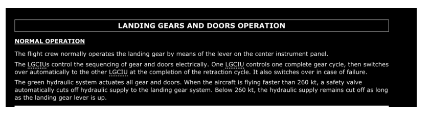
#40. As long as the landing gear lever is up, a hydraulic safety valve closes to cut the hydraulic supply to the gear when the airspeed is ………..?
When the aircraft is flying faster than 260 kt, a safety valve automatically cuts off hydraulic
supply to the landing gear system. Below 260 kt, the hydraulic supply remains cut off as long
as the landing gear lever is up.
#41. In Ventilation system, placing EXTRACT pushbutton switch to override position on ground, Will the Air-cond inlet valve open?
When you set Extract pb / sw to Override, extract fan keeps running, air-conditioning air is
added for ventilation and avionics ventilation sys goes into Closed Config. 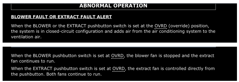
#42. NWS Fault during taxi, BSCU Reset required, Turn back or not?

#43. Fuel CTR TK pumps not in off position and mode selectors left ON in MAN mode, Further consequences?
FCOM PRO NOR SOP 06 OVERHEAD PANEL
IN THIS CONFIG POSSIBILITY OF FUEL SPILLAGE
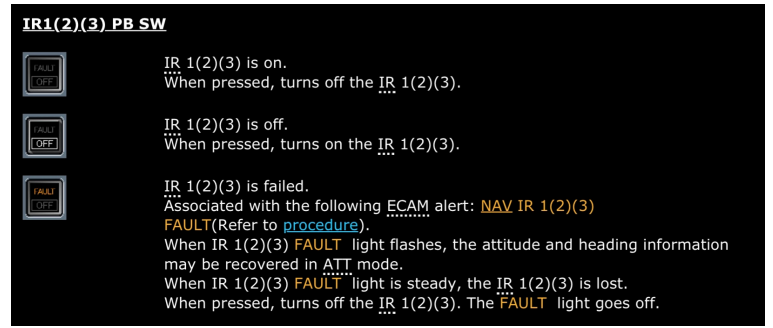
#44. IR Fault light flashing/steady in green in flight?
FCOM DSC 34-NAV 10 20 OVERHEAD PANEL
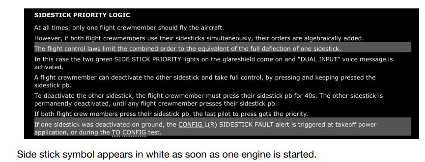
#45. Dual input/priority light logic?
FCOM DSC 27 20 30 LATERAL CONSOLES
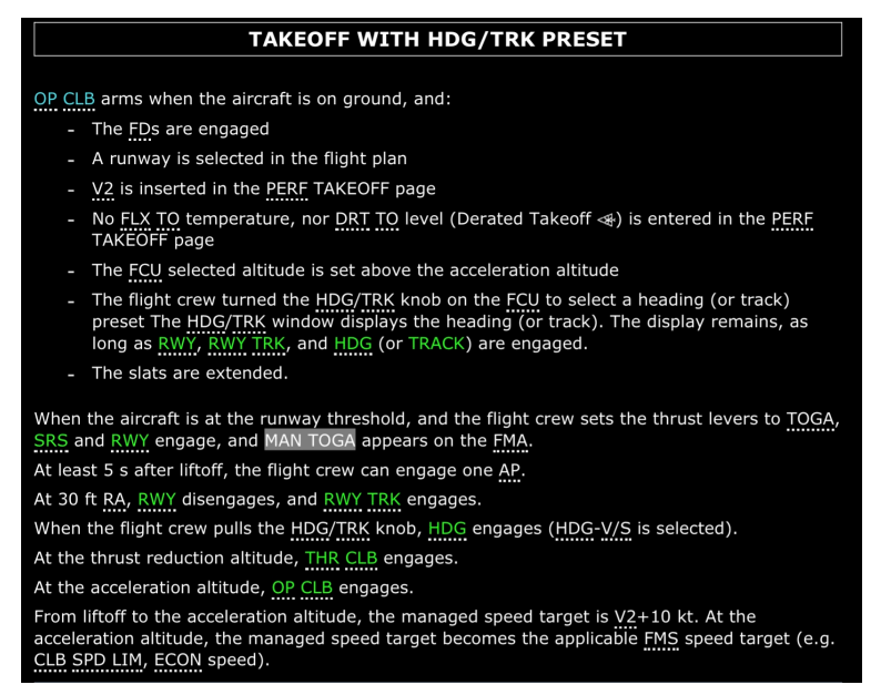
#46. Nav disarmed before take-off, HDG preset, mode after acceleration altitude in pitch?
#47. If a break in both engine fire loops occurs within ………. of each other …… will occur?
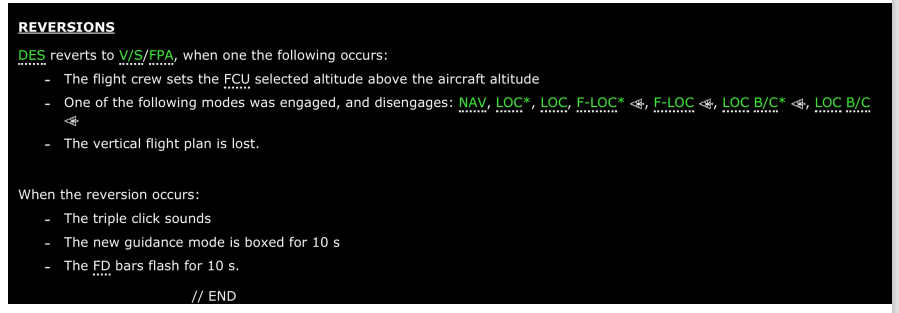
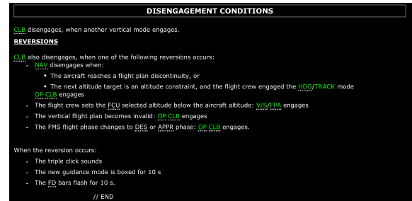
#48. Descending in DES mode and NAV, then NAV disengages, mode reversion?
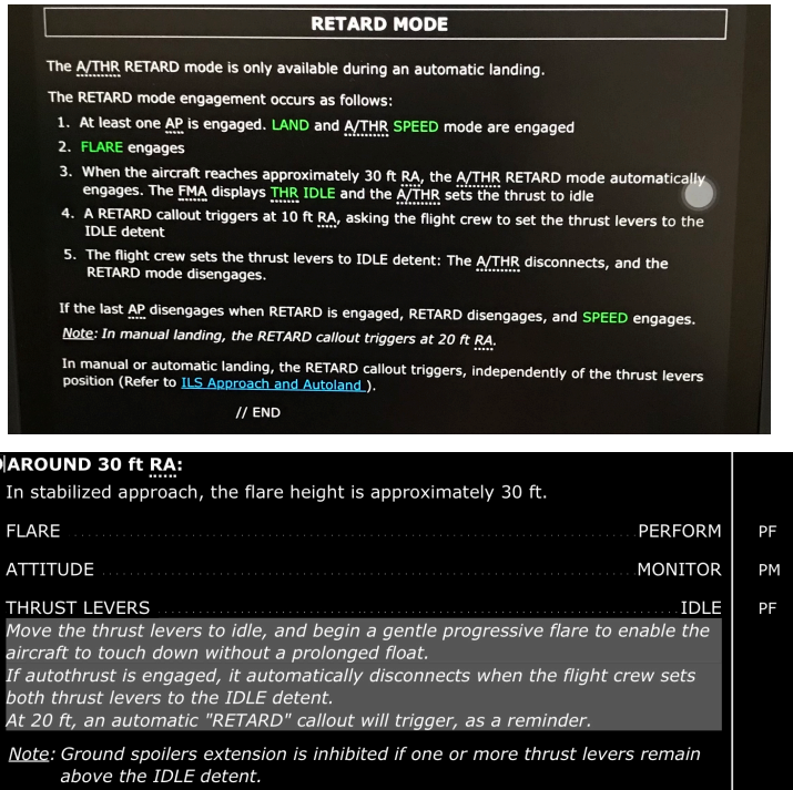
#49. ATHR retard FMA at what height and what conditions?
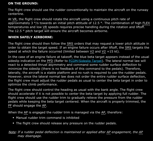
#50. ENG failure at takeoff, procedure and technique to apply rudder?
#51. ENG failure in cruise, immediate actions ?
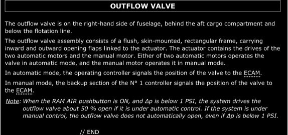
#52. When the RAM air push button is ON with delta P less than 1 psi, position of outflow valve?
#53. Pack flow selector at LO, …..% flow available?
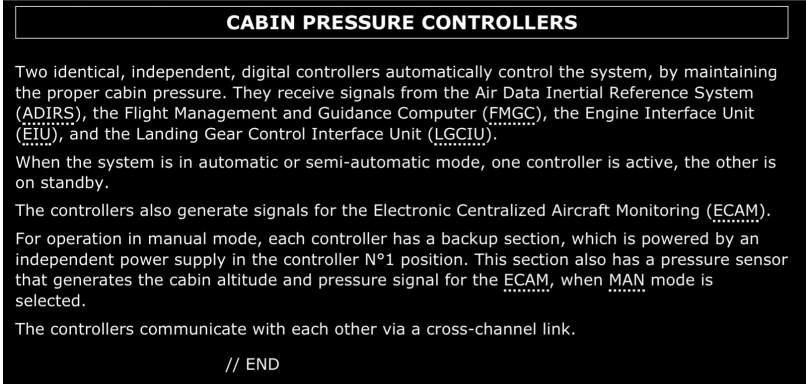
#54. Cabin Pressure Controllers modes of operation?
The flight crew can set the system to operate automatically, semi-automatically, or
manually. In normal operation, cabin pressurization is fully automatic.
#55. Can you recover a Hyd system, if it is due to low level ECAM?
#56. what is a bias?
Each FMGC computes a vector {distance and direction} from its MIX IRS position to the
radio position or GPIRS position.
This vector is called the “bias”.
#57. How many modes of pressurization exist on A320?
AUTOMATIC OPERATION
The flight crew monitors the operation of the system, but does nothing to control it.
Air pressure in the cabin follows schedules from the FMGS.
When FMGS data is not available for automatic pressurization, the crew only needs to select
the landing field elevation. This is called as semi-automatic mode of operation.
The controller normally uses the landing elevation and the QNH from the FMGC, and the
pressure altitude from ADIRS.
If FMGC data are not available, the controller uses the captain BARO Reference from the
ADIRS and the LDG ELEV selection.
MANUAL OPERATION
In manual mode, the flight crew controls the cabin altitude via the manual motor of the
outflow valves,
by operating controls on the pressurization control panel.
When the system is in automatic or semi-automatic mode, one controller is active, the other is
on standby.
In automatic mode, the operating controller signals the po
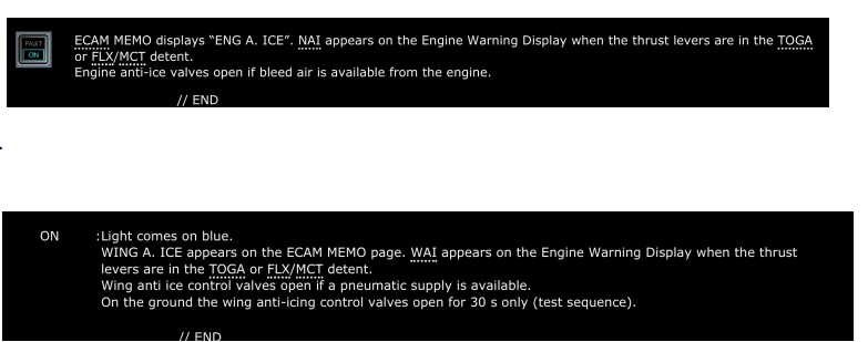
#58. Wing anti-ice valve/ Engine anti-ice valve position when electrical power supply fails?
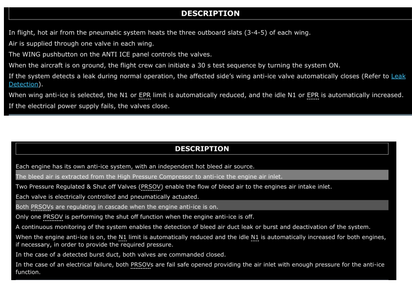
#59. If bleed valve is off, what happens to wing/engine anti-ice valve?
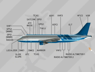
#60. If depth of contaminant at Silchar is less than 2mm and forecast of rain with a Vapp 125kt. What you can expect on landing?
<3mm is not contaminated just WET Notam slippery
when wet Medium to Poor if standing water
#61. With increase in weight, what happens to ROD?
#62. What type of approach is RNP-AR?
NON PRECISION RNAV APPROACH WITHIN A
PBN CONCEPT MIGHT HAVE CURVED FINAL SEGMENTS ALLOWS REDUCED
OBSTACLE CLEARANCE
#63. Fan flutter protection is on which engine?
Keep Out Zone is for protection against fan flutter,
• When on ground at low speed (less than or equal to M 0.1), the Electronic Engine Computer
(EEC) protects engine against fan flutter.
In so doing, the EEC prevents the engine from being stabilized between an approximate range
of 60 % to 74 % N1 (depending on the outside air temperature).
Therefore, during engine acceleration on ground, the pilot may notice a non-linear thrust
response to thrust lever movement and pilot can not set power in the range of 60% to 74% N1
on ground.
#64. Location of DME and VHF antennas?
lg dad tmr below the aircraft
localiser
glide slope
dme1
atc
dme2
vhf2
below the aircraft
#65. 0. FAF (NON-PRECISION INSTRUMENT APPROACH)/FAP(PRECISION INSTRUMENT APPROACH) at what position on Jeppesen charts?
BEGINNING OF FINAL APPROACH SEGMENT INDICATED BY MALTESE CROSS
SYMBOL OR GS CROSSING ALTITUDE INDICATION
The Final Descent Point is the
waypoint from which starts the FMS segment with coded FPA.
#66. While climbing in CLB MODE, NAV disengaged, what mode does it revert to?
FCOM DSC 22-30 40 110 AP/FD MODE REVERSIONS FCOM DSC 22-30 40 40 20
DISENGAGEMENT CONDITIONS
v/s
#67. Take off inhibit conditions/landing inhibit ?
To improve its operational efficacy, the computer inhibits some warnings and cautions for
certain flight phases.
It does so to avoid alerting the pilots unnecessarily at times when they have high workloads,
such as during takeoff or landing.
In these two phases, the DU displays magenta memos: “T.O. INHIBIT” (flight phases 3, 4,
and 5), and “LDG INHIBIT” (flight phases 7 and 8).
#68. when is t.o inhibit active ?
#69. when is ldg inhibit active ?
#70. 3. Avionics VENT/SMOKE system displayed on which SD page?
ECAM CAB PRESS PAGE.
FCOM DSC 21 30 60 ECAM CAB PRESS PAGE
#71. OEI, after 10 min you should be at min acc ht/1500/clean config and GD?
The engine out maximum acceleration altitude corresponds to the maximum altitude
that can be achieved with one engine out and the other engine operating at takeoff
thrust for a maximum of 10 min.
FCTM PR AEP ENG ENGINE FAILURE AFTER V1
#72. Guwahati, RWCC 5/5/4, RWY 20. How will you brief your FO?
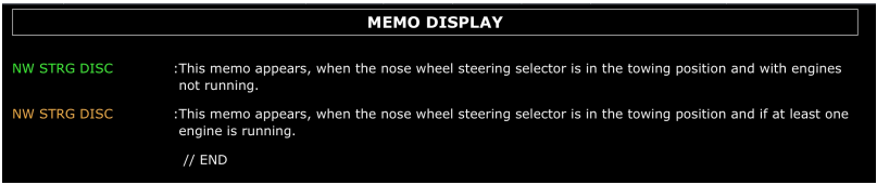
#73. After starting ENG#2, NW STRG DISC amber. Why?
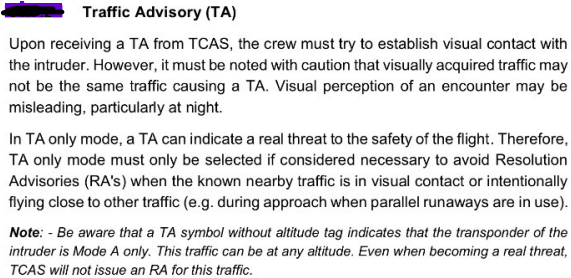
#74. TCAS-TA, PNF to look out to make visual contact with Traffic?
#75. After ENG#1 start on external, AC1 and AC2 supplied by?
Gen#1 supplies AC1 and generally the downstream systems and External supplies
AC2 and generally the downstream systems
#76. Cab Alt warning on ECAM comes at what altitude?
#77. GS Mini, Tailwinds?
#78. Bleed leak, wing anti-ice valve will close?

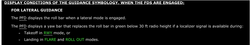
#79. . Yaw bar comes when?
#80. EDTO flight, ETP inserted in MCDU before departure with coordinates. How will it be displayed on ND and when?
STORED WAYPOINT WPT ON ND IN MAGENTA COLOUR WITHIN 160 NM.
OPS MANUAL PART A CHAPTER 4 PAGE A-4-38/370
#81. . Slide armed indications on ECAM are in which colour?
#82. . When will be outflow valve indications are in Amber colour on ground/flight?
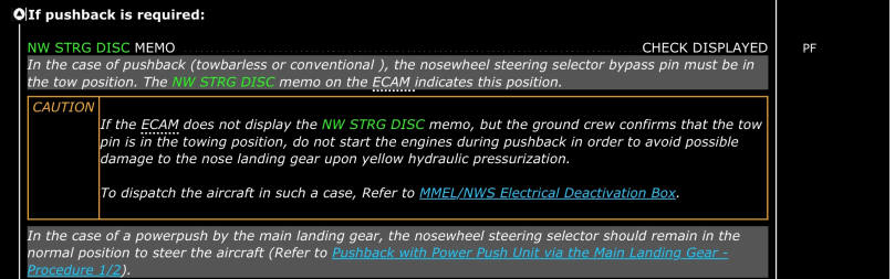
#83. NWS DISC not indicating before pushback. Can we still pushback? When will we start engines?
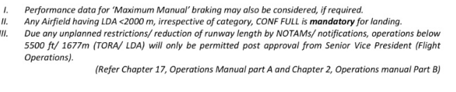
#84. . Length of runway reduced after landing to 5000ft due to cracks found on runway reported by ATC. How will you depart?
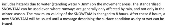
#85. . Validity of SNOWTAM?
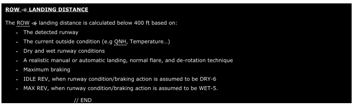
#86. ROW function, wet runway, which reverse thrust will it consider for calculations?
#87. . Landing in Silchar with LDA less than 1800m, company recommendations on Config selection?

#88. BMC1 FAILURE EFFECTS?
FCOM DSC 36 10 20 GENERAL FCOM DSC 36 10 60 BMC FAILURE
If BMC 1 fails, the BMC 2 takes over the monitoring of the bleed system to issue the
following ECAM warnings if necessary :
overpressure
overtemperature
wing leak.
The ENG 1 BLEED FAULT light on the AIR COND panel is lost, and the ENG 1 BLEED
VALVE does not close automatically.
ENG BLEED LEAK warning is lost for the No.1 engine, and
The APU BLEED LEAK warning is also lost.
#89. With the BMC2 failure, what functions are lost?
if BMC 2 fails, the BMC 1 takes over the monitoring of the bleed system to issue the
following ECAM warnings if necessary :
overpressure
overtemperature
wing leak.
The ENG 2 BLEED FAULT light on the AIR COND panel is lost, and the ENG 2 BLEED
VALVE does not close automatically.
ENG BLEED LEAK warning is lost for the No.2 engine.
#90. BLEED LEAK protection for apu pneumatic duct is provided by
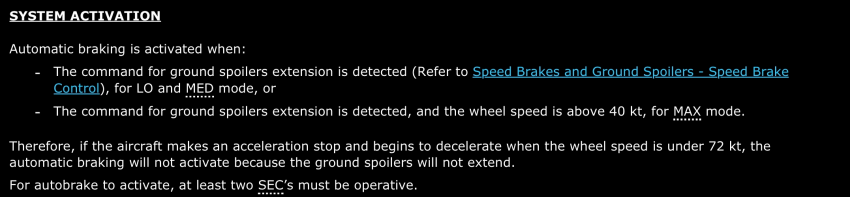
#91. Auto brake activation at?
GRD SPOILERS
EXTENSION
FCOM DSC 32 30 10 AUTO BRAKE
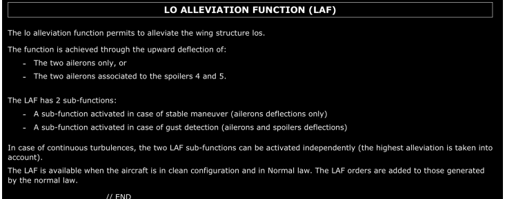
#92. Load alleviation function?
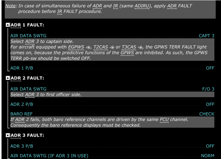
#93. ADR1 fault, switching panel questions?
#94. Check weight message on MCDU?


#95. . Dispatch with landing gear down, which config is preferred?
#96. APU fire red disc not there?
thermal discharge has occured
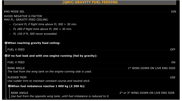
#97. You are cruising at 350 for more than 30mins. What is gravity fuel feeding altitude
current altitude
#98. What approach climb gradient will you use if it isn’t met?
#99. what is climb gradient?
The climb gradient is the rate of climb expressed as a percentage of altitude gain per unit of horizontal distance traveled (typically expressed in feet per nautical mile).
#100. wtb activated when?
flap over run
assymetry
mechanism overspeed
symmetrical runaway
uncommanded movement of surfaces
#101. When does landing elevation fault comes?
This alert triggers when the LDG ELEV selector is set to AUTO and the landing field
elevation of the FMGS is not available
#102. Continuous ignition in IAE engines when?
ENG ANTI ICE is selected ON and/or engine flameout is detected in flight and/or EIU
fails
#103. Avionics smoke which page will appear?
#104. When do you get FAULT light in MODE SEL p/b for FUEL?
Amber light comes on, and ECAM caution { FUEL AUTO FEED FAULT } comes on when
center tank has more than 250 kg of fuel and the left or right wing tank has less than 5 000 kg
#105. When reversers are used, the EPR rating limit on EWD show amber crosses?
The thrust limit value disappears when the thrust reversers are used
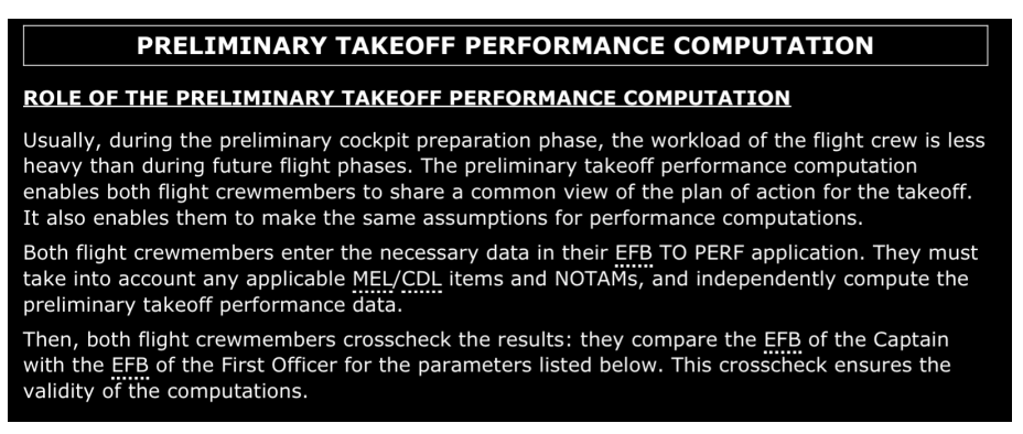
#106. Preliminary take off performance calculation?
#107. During ils, what is the RNP value on progress page ?

#108. If FLD IS 1700 and LDA is 2700 at VABB and wet RWY, what reverser you will select?

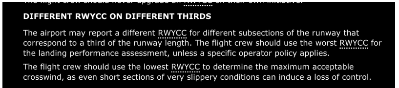
#109. GRF and relation of the displaced threshold?
It reports for each 1/3rd of RWY and it is
available for Take off also
#111. EDTO blue reservoir fault and one Gen inop? Diversion is required?
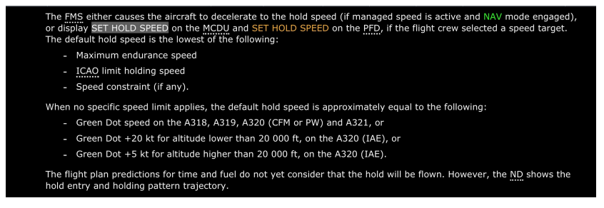
#112. . Holding at destination, what speed you will maintain and why?
#113. TRIP FUEL DEFINITION?
Amount of fuel required for takeoff climb cruise at ci and then landing at the aerodrome taking into account operating conditions
#114. . Battery check in cockpit preparation?
Check on the ELEC SD page that the current charge of the battery is below 60 A, and
is decreasing
FCOM PRO NOR SOP 06 OVERHEAD PANEL
#115. Which condition is not possible?
ome gen on apu and other on gpu
#116. Higher flaps effect?
LDR reduces and second segment climb gradient reduces/an
increase of the field length limited take off mass but a decrease of the climb limited
take off mass
#117. . OEI with anti ice ON?
Rely on EFB for fuel calculations
#118. EWD fails?
Adv on ewd and sd page light will flash
#119. Which mode is not a CPC mode?
Go Around mode
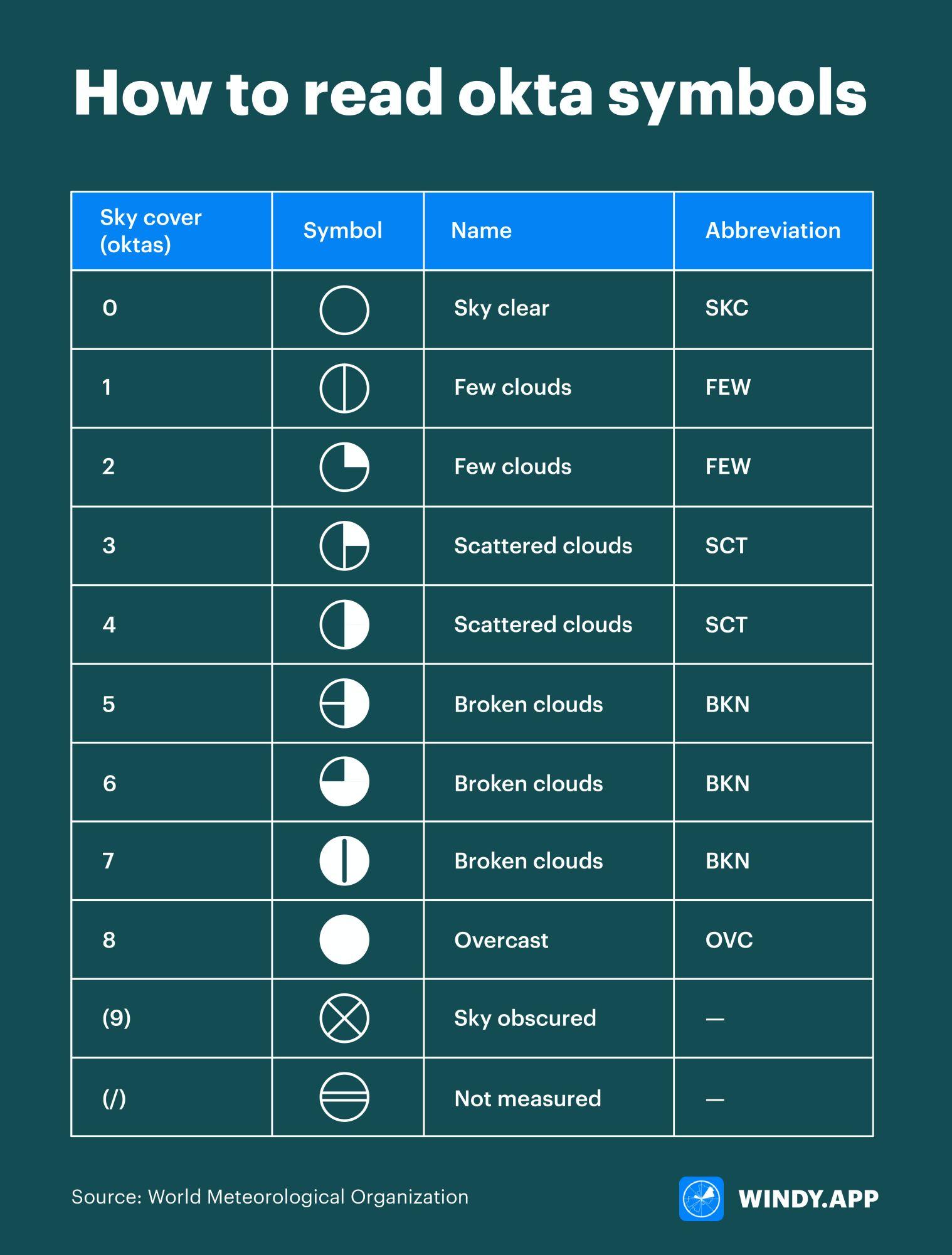
#120. 4. Broken clouds, how many octas?
#121. Centre tank L/R XTR fault light?
Amber light and associated ECAM caution come on, if the associated wing tank
overflows
FCOM DSC 28 20 OVERHEAD PANEL
#123. Oxygen Masks drop when?
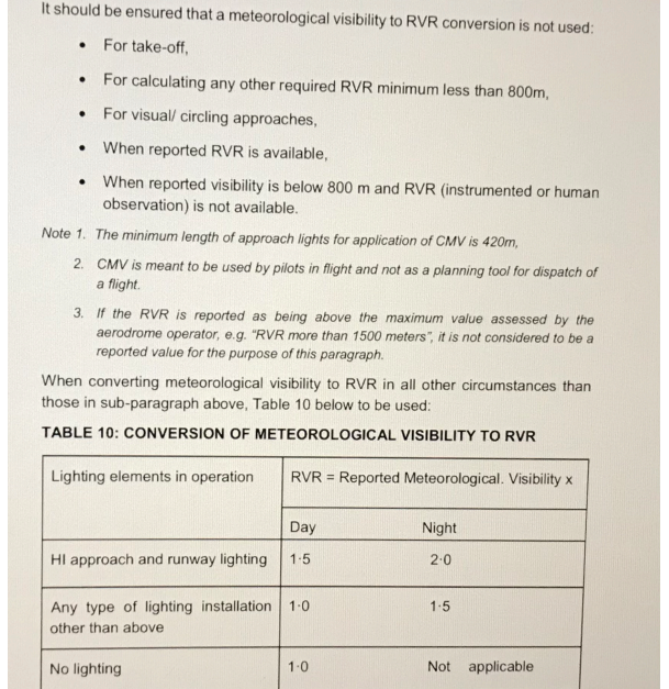
#125. . CMV?
#126. 1. RA1 fault ECAM, what all lost?
FCOM PRO ABN NAV NAV RA1/2 FAULT
CAPT PFD DISPLAYS HEIGHT FROM THE REMAINING FO’s i.e., RA2
#127. RVR 600/125/125? T/O alternate is required?
Yes as it’s LVTO
POLICY AND INFORMATION NOTICE 03-02
#128. Heavy rain in BOM. As per GRF, runway condition code will be available by which means?
In accordance with the new GRF for runway surface condition, the Runway Condition
Report (RCR), when generated, is disseminated to a pilot through the following means :
SNOWTAM and ATIS and/or Voice when the runway is wholly or partly contaminated by
standing water, snow, slush, ice or frost, or is wet associated with the clearing or treatment
of snow, slush, ice or frost; and
ATIS and/or voice only when the runway is wet, not associated with the presence of snow,
slush, ice, or frost.
In other words, when there is no contamination, the RCR will be disseminated only via the
ATIS.
ATIS is an important means of reducing the ATS workload associated with the accurate
and timely transmission of safety and operational information, including runway surface
conditions, to flight crew. The responsible ATS unit will update the ATIS message when
they receive information concerning runway surface conditions through an RCR. With the
implementation of the GRF, some additional clarifications relating to the RCR- related
syntax of ATIS messages are necessarv
#129. Kathmandu, 2mm water. What aquaplaning you can expect? Dynamic, Viscous, steam/Reverted Rubber
aqua planning will occur only if the runway is contaminated , i.e more than 3mm
#130. What is SRS speed guidance during T/O with both engines working?
Speed Reference System is a vertical mode which controls pitch to maintain a speed defined
by SRS guidance (provided V2 is inserted in the MCDU PERF TO page, the slats are
extended, and the aircraft is on the ground).
It is v2 15 kt.
#131. What is SRS speed guidance during T/O in single engine?
When the FMGS detects an engine failure, the speed target becomes the highest of
V2 or current speed, limited by V2 15 kt.
#134. When will SRS disengage automatically after T/O in case of single engine?
In Engine Out conditions, the SRS mode does not automatically disengage at EO
ACC ALT
#135. What is SRS speed guidance during G/Around with both engines working?
The SRS law maintains the current speed at Go-around engagement, or VAPP, whichever is
higher.
Nevertheless, the SRS speed target is limited to VLS 25 kt, in a two-engine configuration
#136. What is SRS speed guidance during G/Around in single engine?
The SRS law maintains the current speed at Go-around engagement, or VAPP, whichever is
higher.
Nevertheless, the SRS speed target is limited to VLS 15 kt, in an engine-out configuration.,
#137. When does the RWY mode engage?
Mode used at takeoff to guide the aircraft along the runway centre line, using LOC.
Triggered by the thrust levers at FLX or TOGA position.
Remains engaged until 30 ft after T/Off.
#138. When does the RWY TRK mode engage?
At 30 ft, RWY TRK is annunciated until the HDG/TRK knob is pulled
#142. What happens to the symmetric surface on the other wing, when a speed brake surface (on one wing) fails?
When a speed brake surface on one wing fails, the symmetric one on the other wing is
inhibited.